Quick bit of background for this: I'm currently in the
process of putting together a simple analog sequencer
for a barebones DIY synth thing, this is just a part of
that process that seemed worth sharing.
[2024 update] Ported this post from cohost to this website,
as I'm still quite proud of it. The sequencer spoken of above is finished
but I need to make a full schematic. It will go up here
whenever that ends up getting done
Here's an image of a super simple oscillator.
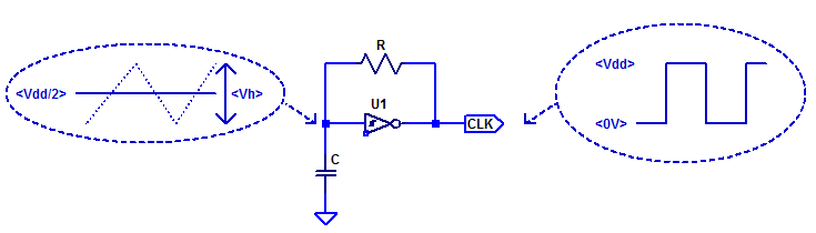
A full explanation of how it works can be found via
the link at the bottom of the post. All you really need
to know is that, when the circuit is powered with 12V,
the voltage across the capacitor merrily ping-pongs
between ~4V and ~7V. So if you want to reset the
oscillator (this is what hard sync requires), the voltage
across the capacitor needs to be set to 4V as quickly as
possible. This is the design that ended up working.
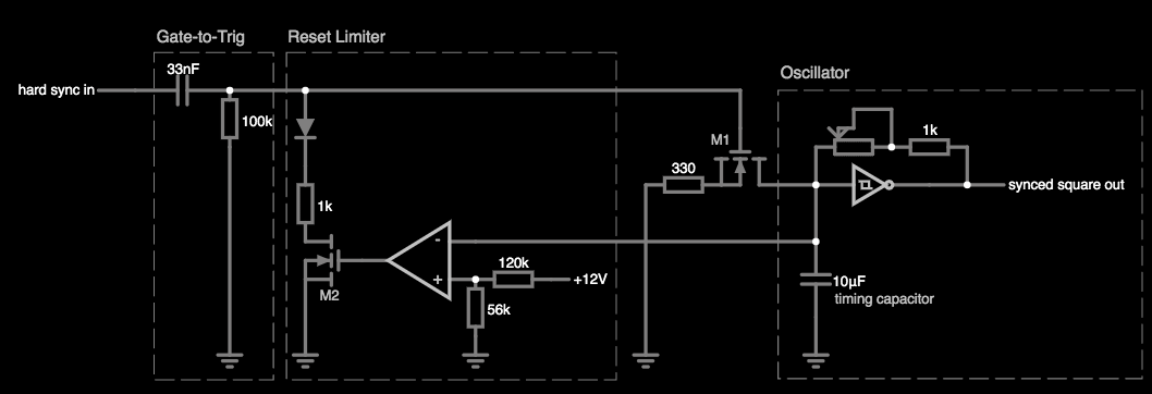
Here's
a browser based simulation of it! Circuit breakdown
incoming, skip 3 paragraphs if you don't wanna
hear it :)
It's safe to ignore the reset limiter section for
the moment. M1 (an N-channel MOSFET) is the key
component that controls when the timing capacitor is
reset to 4V. It's acting as an electronically controlled
faucet. When the voltage at the gate input
(the topmost connection, the one that the arrow is
pointing towards) is at ground (0V) the MOSFET is off,
so the faucet is closed, and no current can flow through
the other two terminals. Conversely, when the voltage
at the gate input is greater than 2V, the MOSFET
turns on and current can flow through the other
two terminals. Specifically, current will flow out of
the timing capacitor through the 330 ohm resistor
to ground. In doing so, the voltage across the
capacitor will lower quickly.
The gate-to-trig converter restricts the amount of
time that the MOSFET allows current to drain out of
the timing capacitor. A low-to-high (0->12V)
transition at "hard sync in" is transformed into a
short pulse by the converter. This short pulse
appears at the gate of M1 causing it to turn on,
thereby discharging the timing capacitor for the
length of the pulse. However, the constant length
of this pulse means that the capacitor could easily
discharge more than is required, the voltage across
it dipping too far below 4V. This would cause
timing inconsistency, so the reset limiter is required.
Without going into specifics, the reset limiter
sub-circuit measures the voltage across the timing
capacitor, and turns off M1 if the measured voltage
dips far enough below 4V. The end result is this: whenever
a low-to-high transition is present at the
"hard sync in", the voltage across the timing capacitor
is rapidly drained until it reaches 4V, at which
point the oscillator carries on oscillating normally. Phew!
If you're familiar with the super simple oscillator
you might've seen another way to do syncing that
was a lot simpler than this one. Just put a diode
with its positive side to one oscillators output and
negative side to the timing capacitor like so
(ignore the stuff on the right).
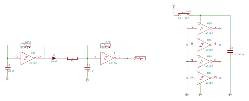
Turns out this isn't really a sync at all! The leftmost
oscillator just stops the other from running for half of its wave cycle
(i.e when 12 is high, 2 is forced low). It's essentially
slightly weird amplitude modulation, great for making
cool timbres at audio frequencies, but at metronome
frequency and for my specific application it is less
useful.
Thanks for reading!
Notes: https://2n3904blog.com/cd40106-schmitt-trigger-relaxation-oscillator/
back